Building a 42-Key Corne Split Keyboard - Part 2
Fumbling with a Soldering Iron
2023.12.02 - Connor Shugg
Mechanical Keyboards
Ortholinear
Split
Corne
CRKBD
Soldering
Electronics
In the last blog post I went over all the materials I bought to build crkbd, or the Corne Keyboard, a 42-key split ortholinear keyboard. With all the pieces and the right tools assembled, I got to work with the soldering iron.
The Diodes
Diodes are very small components that allow the flow of current in one direction, but forbid the flow of current in the other direction. Each of the 42 keys across the two halves of the keyboard had a diode to solder. I soldered these to the PCB before anything else. They are very small and required careful handling with a pair of tweezers:
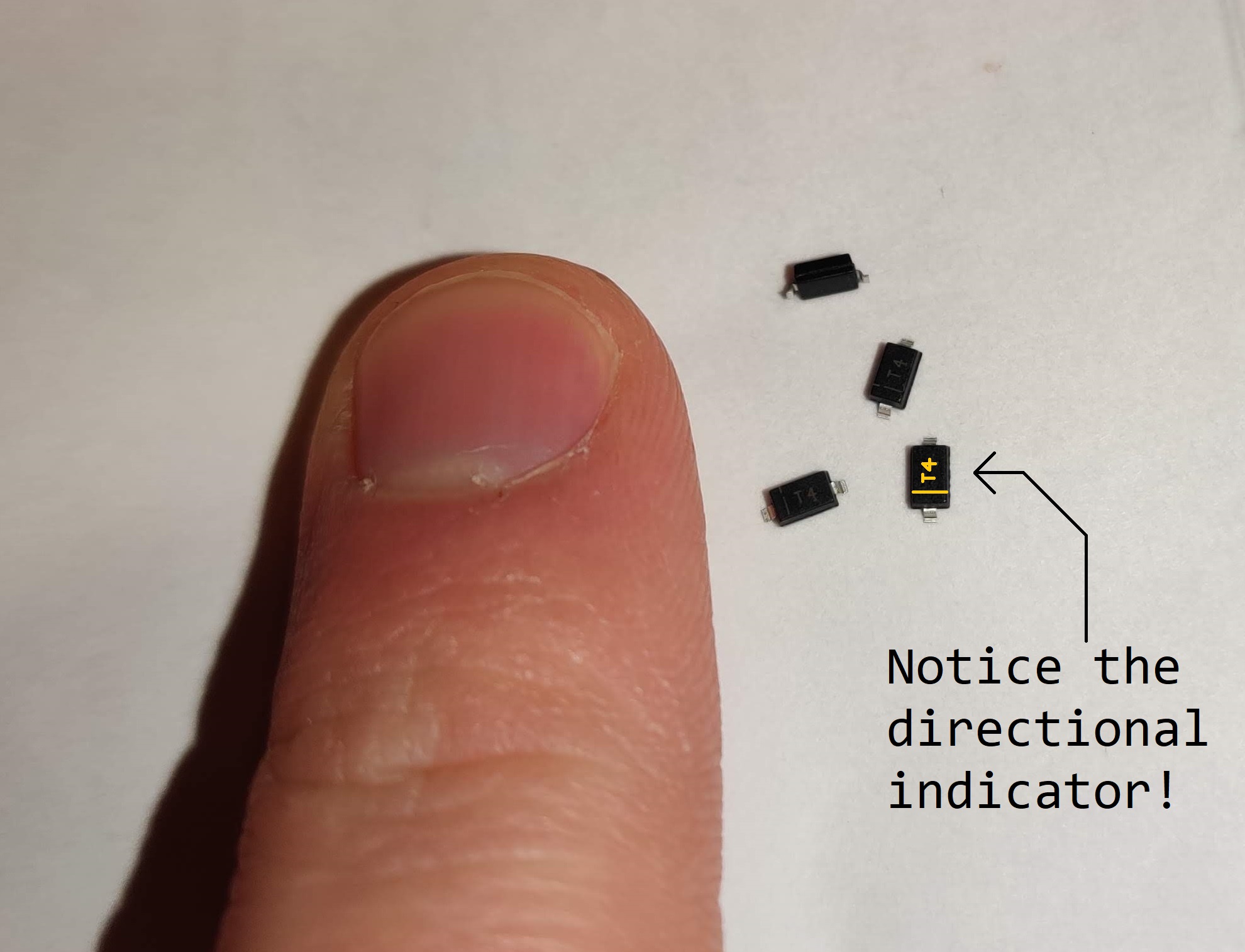
The diodes are mounted on the surface of the PCB, and each requires to separate pads to be soldered (to join both sides of the diode to the PCB). I applied solder to one pad before putting the diode on, then re-flowed it later to stick the diode in place:
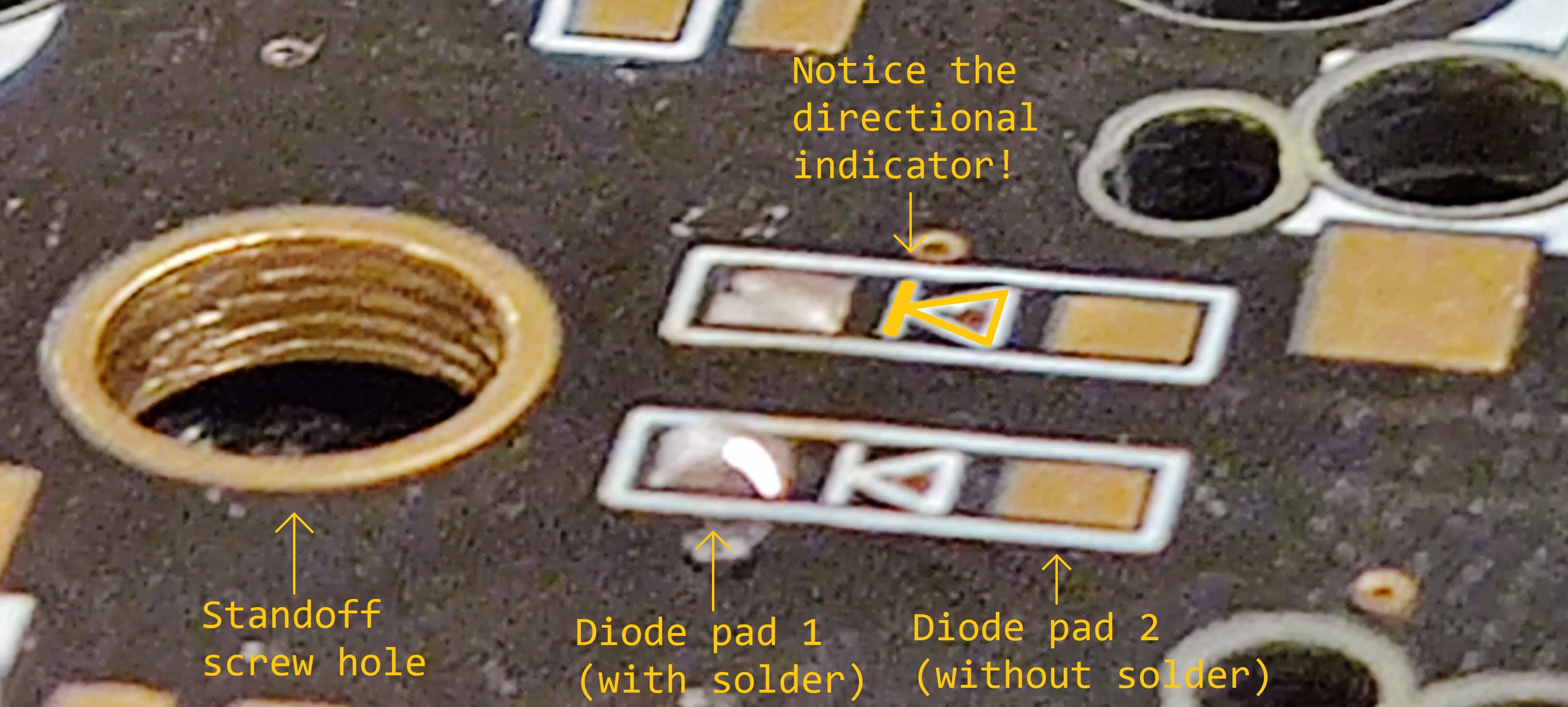
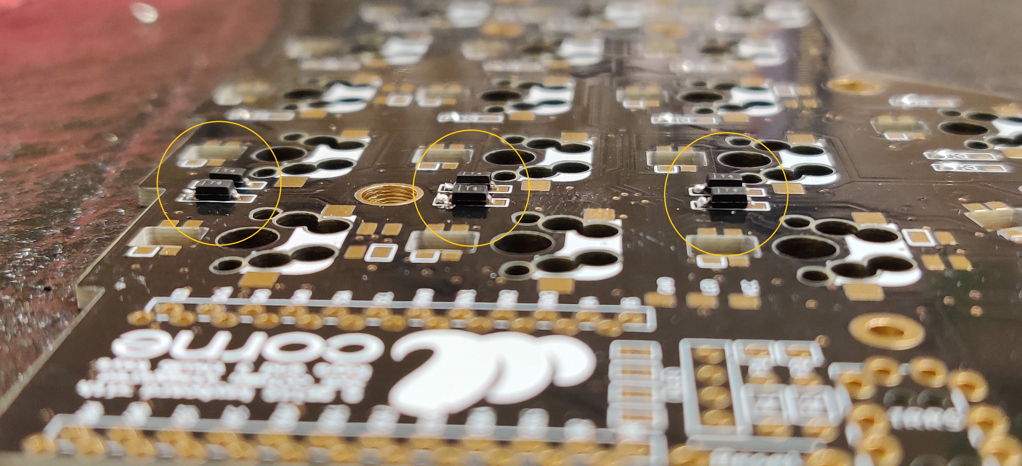
The diodes were arguably the hardest part of the build. They’re very small, and you have to ensure you’re soldering them on in the correct direction. Once these were finished, I moved onto the Kailh sockets.
The Sockets
The Kailh sockets I ordered with the kit are known as “hot swap” sockets, which allows you to easily remove your keyboard switches if you ever decide you want to install different onces. Each socket has two housing where the switches’ pins sit:
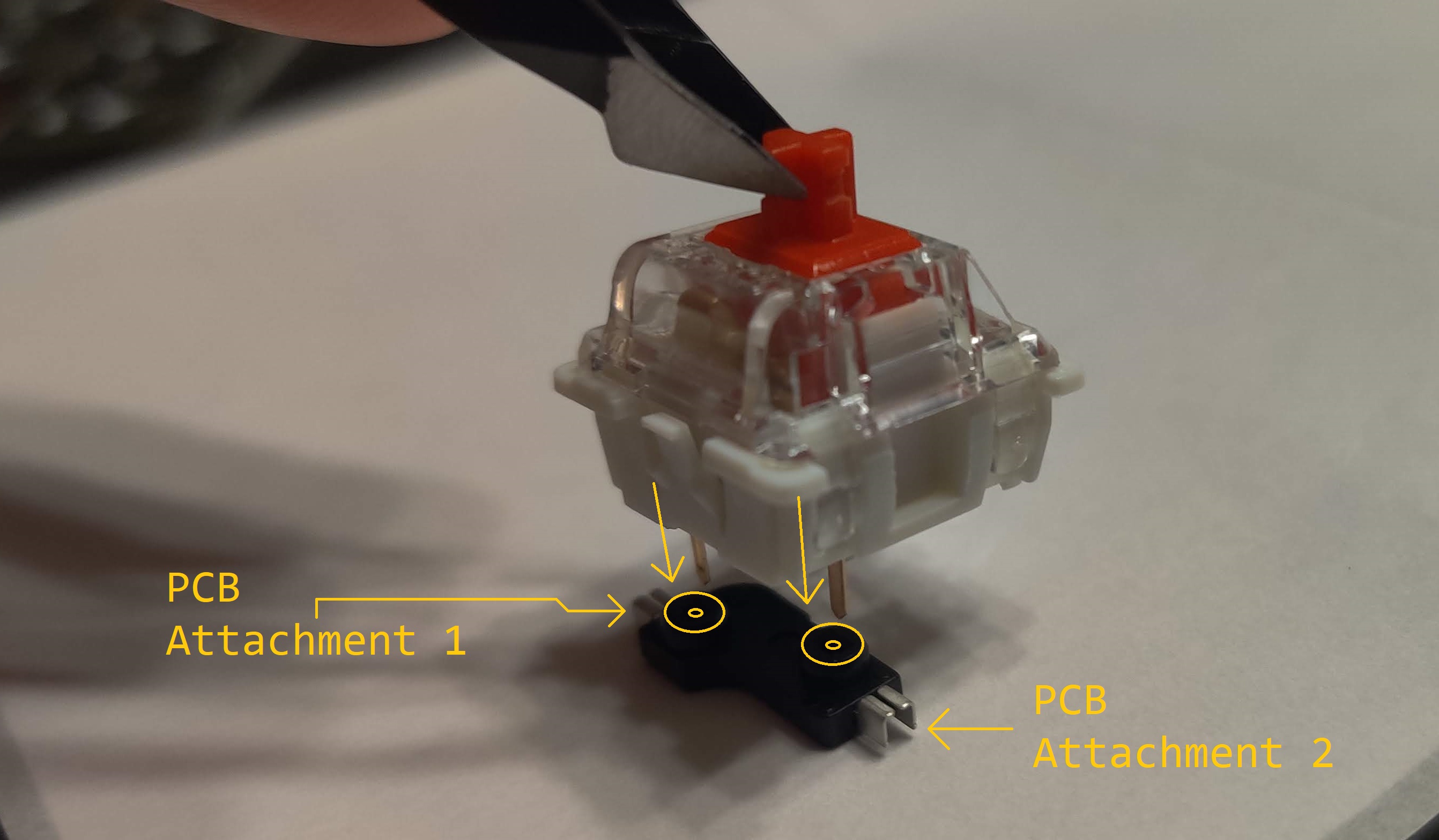
Thankfully, the sockets are larger than the diodes, so it’s not as difficult to position them on the board. However, like the diodes, they have two contact points that need separate solder joints to the PCB. I used a similar strategy with the diodes to stick one side of the socket to the PCB before soldering the other side.
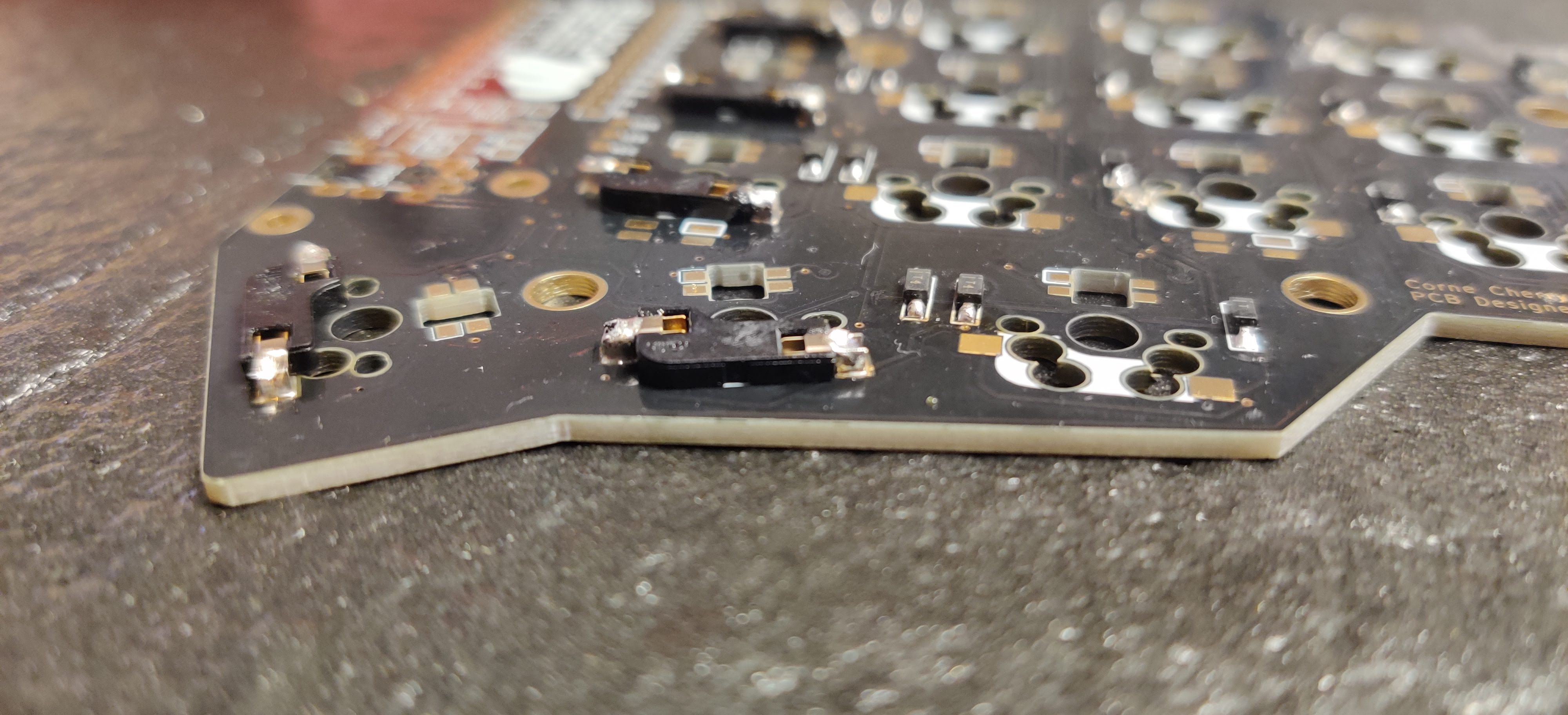
It’s important to note that the two pin holes on the socket are upside down in this picture. That’s because this side of the PCB (where the diodes and sockets are) is acting as the bottom side. The top side of the PCB will have the switches and keycaps.
TRRS Jacks and Reset Switches
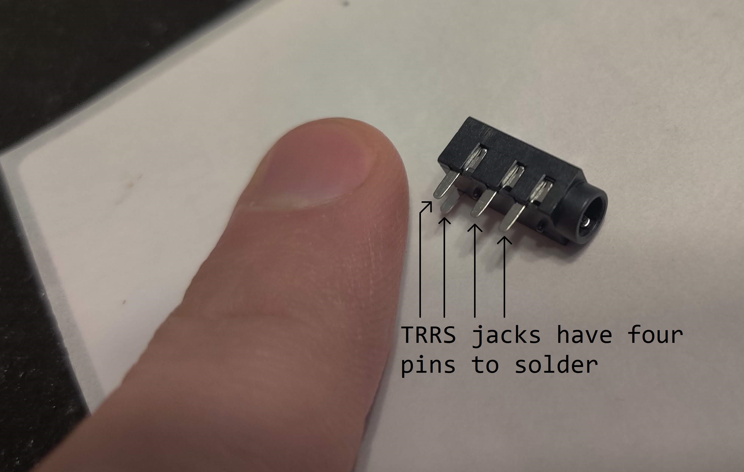
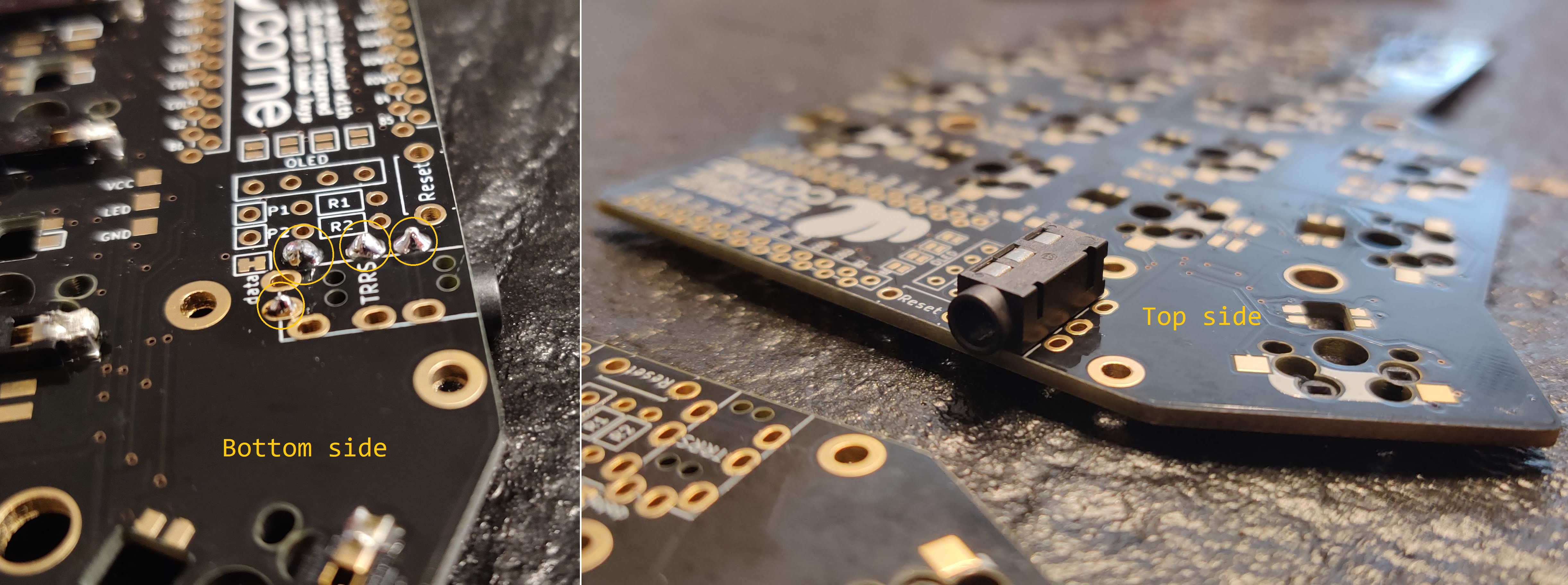
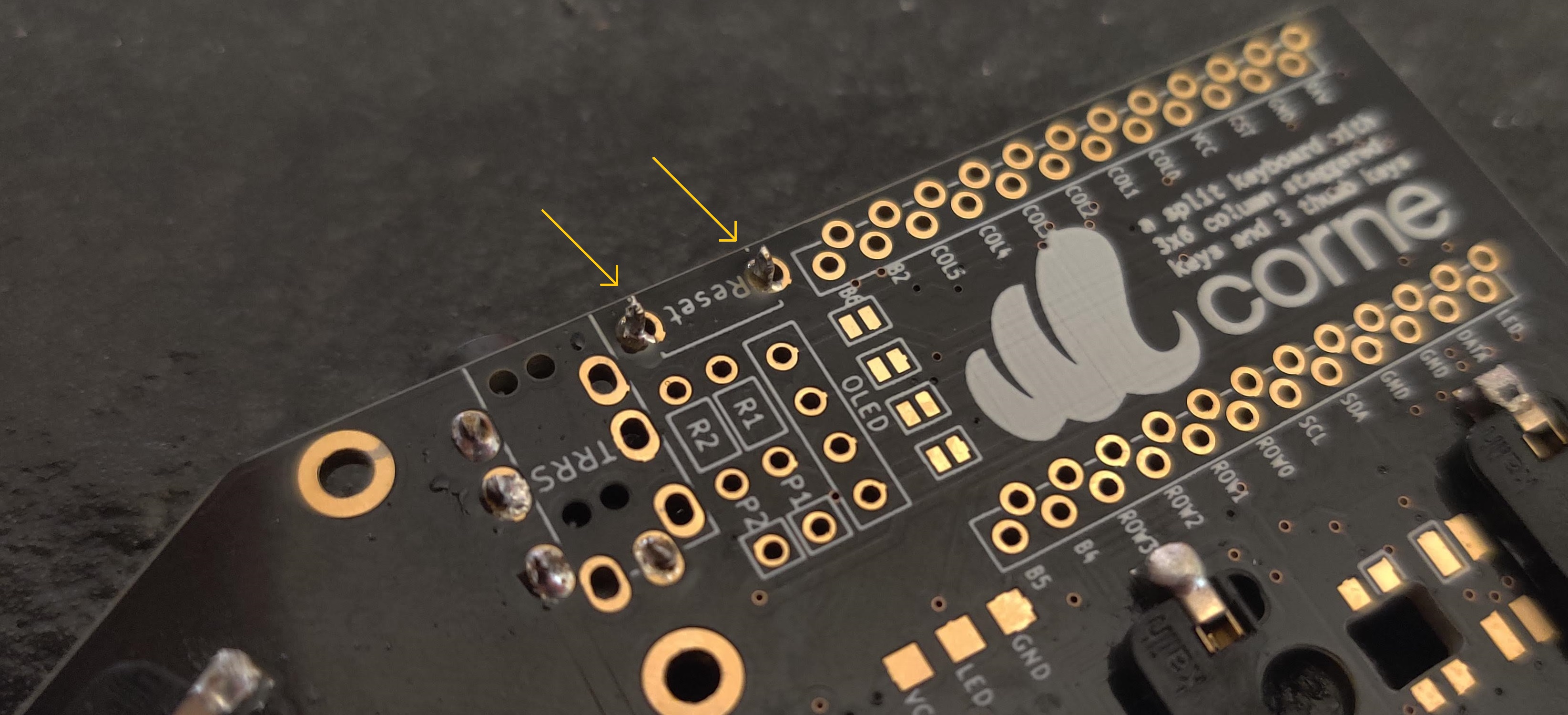
With all 42 diodes and sockets installed, I moved onto installing the TRRS jacks and reset switches. The TRRS jacks are used to join the two sides of the keyboard together via a TRRS wire. each PCB needs a TRRS jack soldered to the correct location.
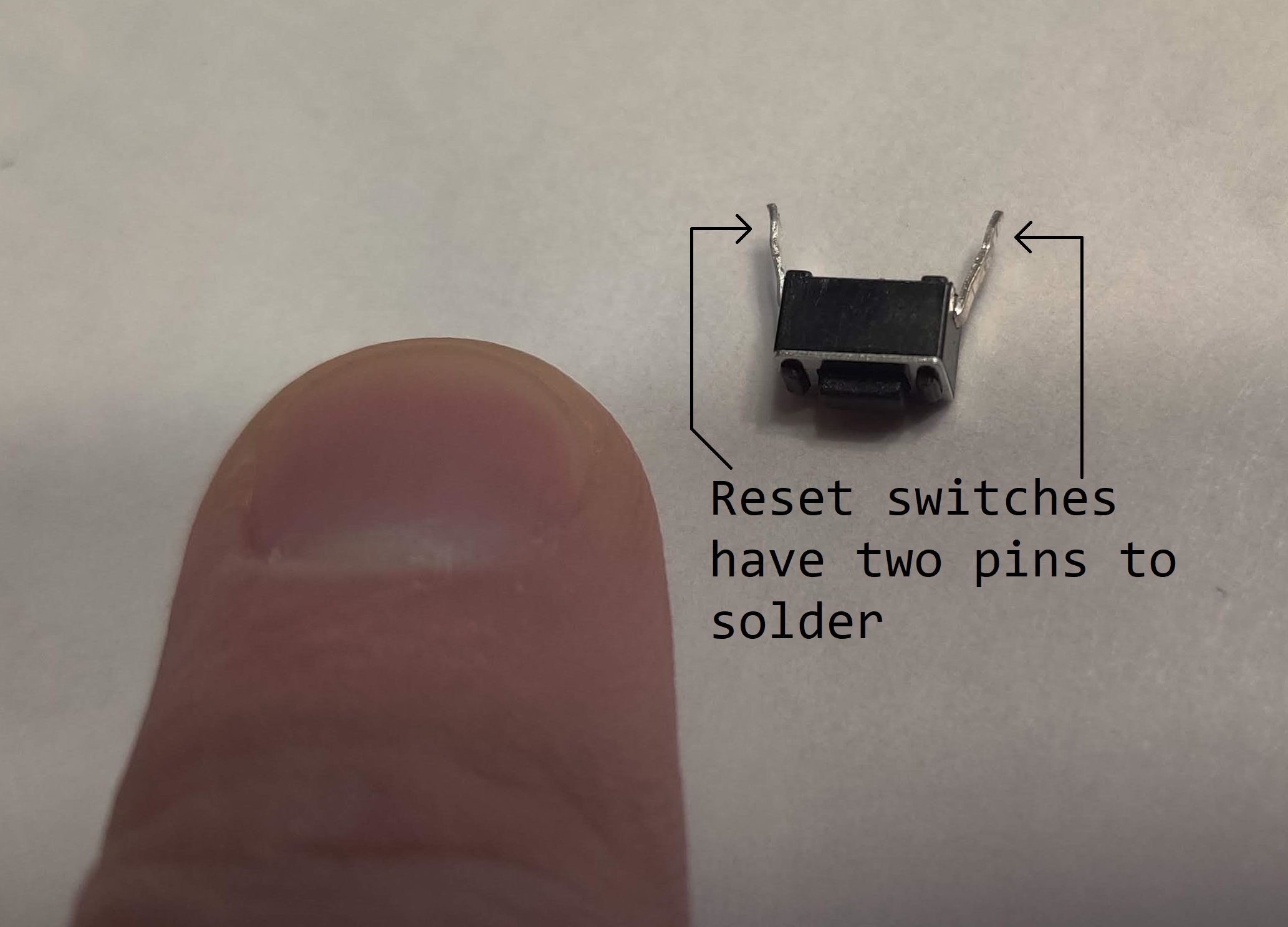
The reset switches are used as a quick and easy way to trigger the microcontroller’s reset mode on each PCB. When in reset, new firmware can be flashed to the microcontroller. Adding these buttons makes it much easier to update firmware on the keyboard; no disassembly required!
Microcontrollers
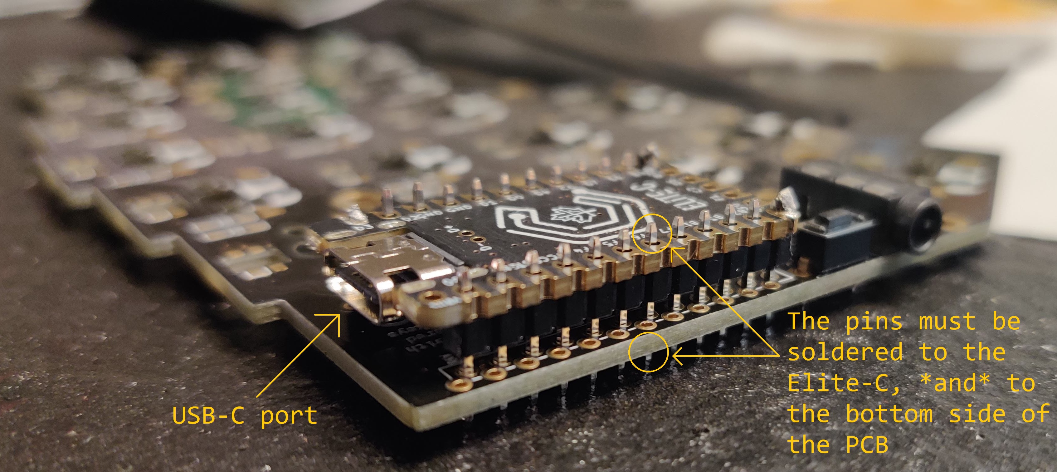
Soldering the two Elite-C microcontrollers was careful work. They each have 24 pins, and each pin needs soldering in two places:
- First, the pins themselves need to be soldered to the pin-holes on the Elite-C.
- Next, the other end of the pins need to be soldered to the PCB.
For obvious reasons, the USB-C port must be pointing away from the PCB, so a USB-C cable can be plugged in to power the microcontroller.
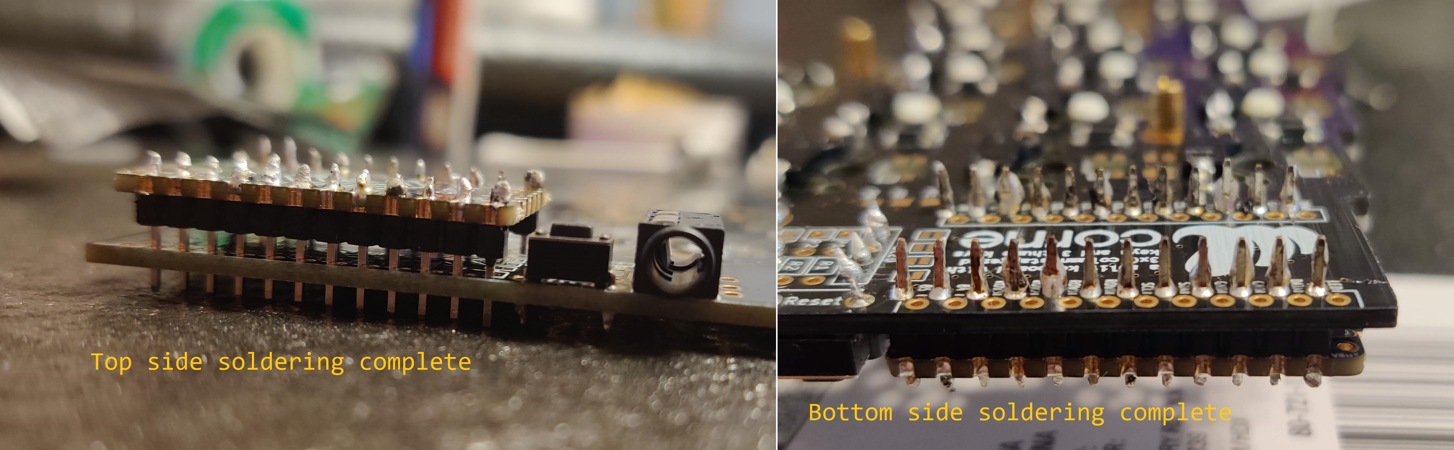
I took my time with this part, ensuring I didn’t accidentally create a bridge between two adjacent pins on the Elite-C. Doing that would likely create some strange issues with the microcontroller’s behavior, and the entire keyboard wouldn’t work properly as a result. I also was careful to spend as little time as possible with the soldering iron’s tip on the microcontroller. Heating up the microcontroller too much can permanently damage it.
OLED Screens
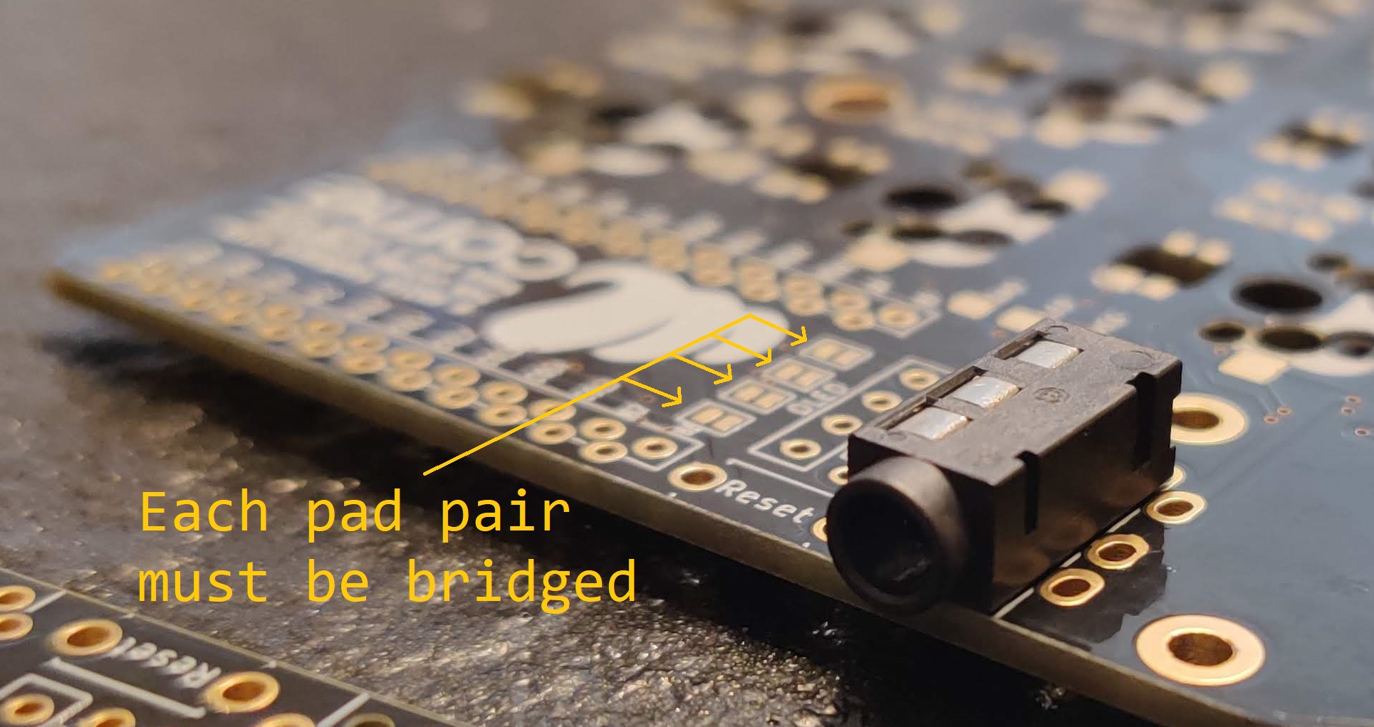
While working on the Elite-C, I also did intermittent work on the OLED screens. Four jumper pads on the PCB must be soldered together in order for the OLED screens to work. It’s much easier to solder these before soldering the Elite-Cs to the PCBs:
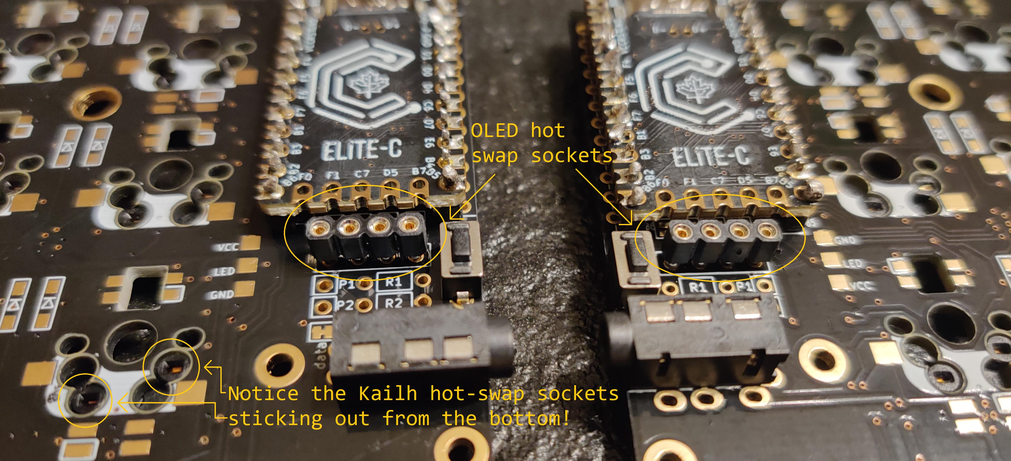
After that, I soldered hot-swap sockets to the PCB for the OLED screens. These allow for the OLED screens to be replaced in the future, should the need arise:
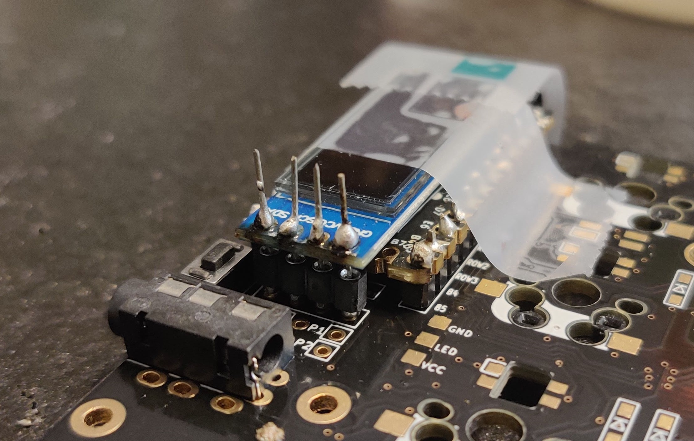
To get the OLED screens to fit in the hot-swap sockets, I had to cut out some extra wire I had lying around and solder it to the four pins on the OLED. To do this, I jammed each of the four wire pieces into the hot-swap sockets, then laid the OLED screen on top, using some scotch tape to keep it all in place. Then, I soldered the wires to the OLED’s board, and cut off the excess.
With that, everything was soldered and ready to go. The result:
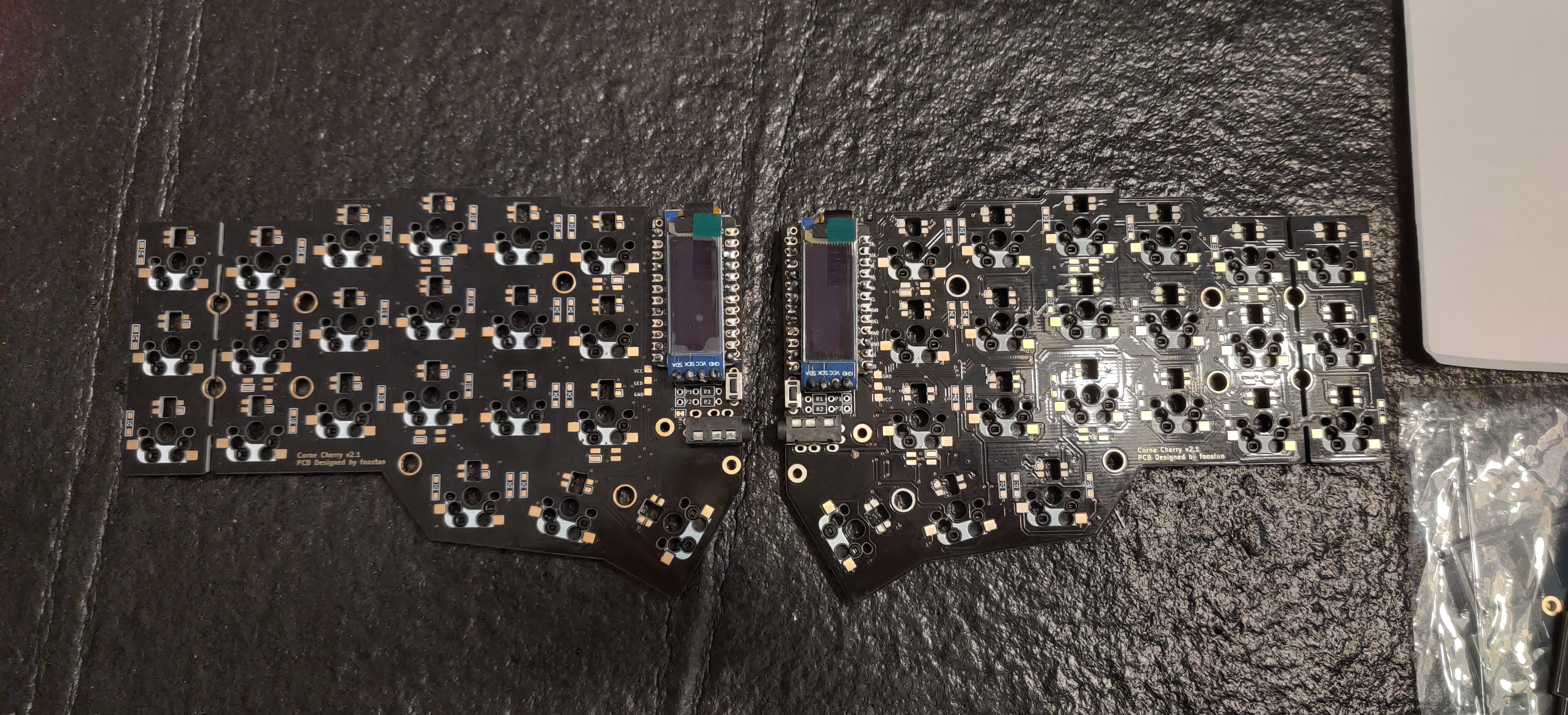
Next up? Installing the mechanical switches, installing the keycaps, wrapping it all up in the case, and flashing some firmware!